build

Autogyro Bits

IMG_20190530_204954956.jpg


As promised, here’s an update on the mini autogyro I’m building. It’s taken a bit longer than I planned, but I decided to do a build video as I went along. The picture shows the plans with the depron fuselage dry fitted and the hard balsa rotor supports in the bottom right awaiting glueing. I’m still stuck on the ESC and also the motor, so I’ll probably buy some new bits and substitute my 6g servos for 1g ones at the same time. All up weight for the components you see here is 14.2g and I still need to add gear and rotors. I had a 30g budget for equipment, so I’m aiming for 50g flying, which puts it into the same class as a HobbyZone Champ.

OK, I need to go now as the plan is to film the assembly of the rotor supports tonight. It always takes twice as long to do anything if you have to film it.

Rain, Sleet, Snow

We’ve had all three forms of precipitation in the last few days. There’s been heavy rain since 6 o’clock this morning and we might get sleet and snow later, so it’s fairly obvious that there’s not going to be any flying done this week. I haven’t flown the RS352 since the week before Christmas now. My BMFA renewal arrived earlier this week, so I’m good to fly for the whole of the rest of the year. It’s always like this every January.

The little blue acrylic quadcopter is flying around indoors nicely though. You can see that I have added some basic prop guards since last week. I’m actually a bit disappointed with the weight as it’s come out at 48g flying weight, while I was hoping for a bit lower. I’ve still got to add the 4g FPV camera, but the test flight this morning was around 5 minutes. That suggests that it’s round about the same as the HubSan X4C, although the flight controller is in a different league. The separate flight controller and FrSky receiver that you can see in the picture above must be heavier than one of the integrated units, so I must be giving away a few grammes there. I’m flying it with my Futaba Field Force 8 which has a FrSky ACCST module in the back. This is what makes me really mad about FrSky, because I can’t use the Taranis radio with this receiver. Our Taranis for work was flashed with the European firmware and that won’t talk to an 8 channel receiver, so I’m sticking with the Futaba. Either that or we’ll have to switch everything back to the US firmware.

Anyway, it was refreshing to fly a quadcopter that I’ve actually designed and built myself. It’s just a bit too much of a conventional design, though, so I might have a go at some more radical alterations next. As for this morning’s first full test flight, I took some video using my RunCam, but it’s not that good, so I’ll have to try another flight later today. Also, I don’t think it’s calibrated properly as it was trying to yaw left all the time. This might be to do with the fact that I hold the flight controller on with double sided tape and the flight controller has a habit of peeling itself off where the components on the back don’t make a flat surface. It needs a better solution really, but it’s so easy and light to hold the flight controller and battery on with tape.

As for the balancing of the autogyro blades last week, that turned out to be harder than I thought. There is only a few grammes difference between the heaviest blade and the lightest, but glue doesn’t add that much weight, so it’s hard to get them to balance. I’m not sure how close they need to be, so I ended up trying to take some wood off of the heavier one, but they’re still coming out as 19.2g, 19.4g and 19.9g. That’s within 0.7g, so it’s probably close enough. When I finally cover them with film it’s going to cause the same balance problems all over again.

That’s it for this week, except to say that I now know how to make the Taranis work as a joystick with our flight simulator. You can reprogram the ranges to match the ranges that Unity expects, so it is perfectly possible to use it as a joystick in other software that was written in Unity too. FPV Freerider is one which immediately springs to mind. So that’s my afternoon planned out: film acrylic blue flying, add the FPV camera, play with Taranis and flight simulator.

Let’s hope it’s not raining next week.

Nuisance Drizzle

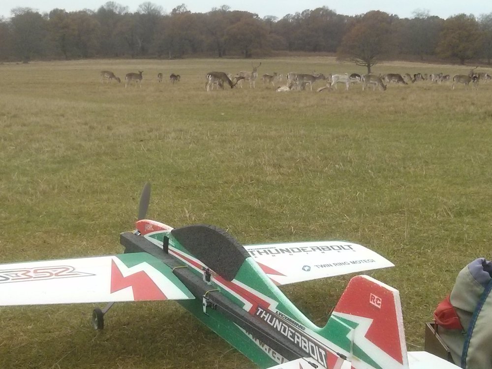
I’ve replaced all four servos in my RS352, so I really wanted to do a test flight this week. The weather forecast showed that it was always going to be marginal with fog and drizzle predicted, but with absolutely no wind. Perfect for a test flight if it turns out to be flyable. The weather in the morning was very damp and drizzly as predicted, but I decided to give it a go anyway. It looked like it was brightening up, so I got in the car, went a little way down the road and then gave it up. There was a lot of rain on the windscreen and it was looking progressively more overcast, so I didn’t get my test flight in this week after all. At this point I should put a note on the aircraft so I don’t forget that it must be out of trim. Bearing in mind how much I’ve flown the RS352, I’m very likely to forget and launch it next week, only to remember when it’s in the air. I doubt it’s all that far out of trim though, as the carbon push rods allow me to get the new servos in position to millimetre accuracy.

Getting back to this week, I’ve been building my own micro quadcopter.

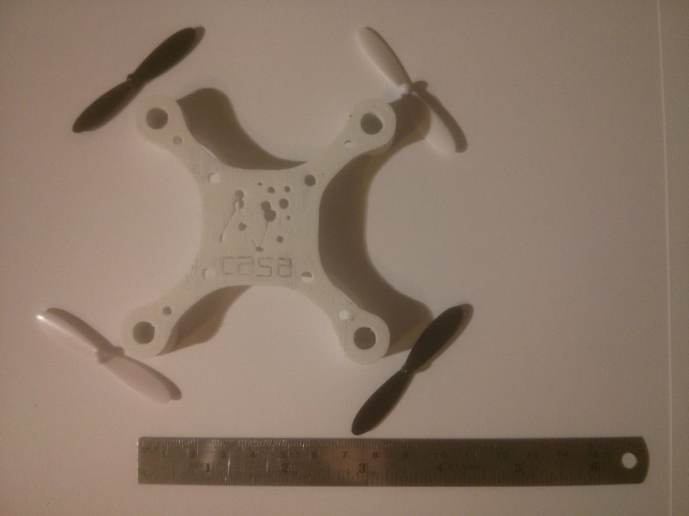
Quadcopter frames aren’t as complicated to make as fixed wing aircraft, but they’ve traditionally followed the route taken by helicopters of buying plastic and carbon bits that you screw together. There are a lot of 3D printed ones, but I’m fed up with 3D printing as it’s not accurate and the prints keep failing. Also, the printers cost thousands of pounds, so it’s an expensive solution. Making your own frame from scratch is very easy to do and is a lot of fun, so I don’t understand why more people aren’t doing it? I built the DaVinci Aerial Screw in the Summer and have been doing some tests to come up with a plan for a frame that anybody can make. Also, the frame I’ve just made weighs 5 grammes. That’s half the weight of a similar 3D printed one.

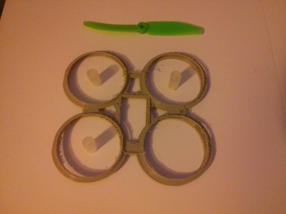
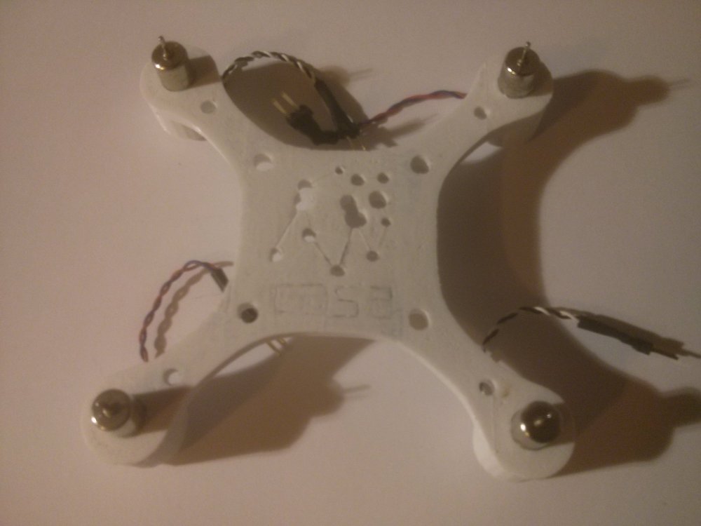
This version uses a piece of A4 vinyl sheet which I bought in Paperchase. I made a paper template and cut out a top and bottom in vinyl using scissors. In between there is a sandwich of Depron which is from an old pizza box base. The four plastic tubes for the motors were just an old bit of tube that I found lying around and drilled out to accept the motors. You could probably use an old felt tip pen barrel, but I’ve also got some other ideas about how to attach the motors which might be easier to construct. One other point worth mentioning is that the cyano I’m using causes my black pen marks to run horribly. In the photos above, the clear blue picture is the bottom, while the one with the smudged black pen marks is the top. I’m going to swap the top and bottom around as I really like the blue and white colour.

As you can see from the set squares, I’ve had to build it very accurately in order to make sure that the motors are all at 90 degrees to the frame. I taped the top and bottom vinyl together in order to drill the holes through both so that they line up perfectly. Then the bottom was cyanoed to the Depron. I’m using a cyano with a fixer spray so that I have a bit of “grab”, but I am still able to position things without it sticking immediately. This gives me a bit of “fiddle” time. Once the bottom was stuck, I used a reamer to open up the holes in the Depron, put the motor cylinders in place and used them to locate the top vinyl sheet accurately. I only glued the centre of the top vinyl up to about 20mm from the motor holes in order to locate it. I removed the motor cylinders before it stuck as I need to ensure that these were square.

The final part was to file out tiny amounts from the motor holes to ensure that the motor cylinders went in square, then weighed everything down while I added the final cyano to stick the last bits together.

I’m relying on the fact that I squared off the tops and bottoms of the plastic motor tubes, so, by weighing it down on a flat surface, I guarantee that all four motors are square to one another, even if the frame might be slightly out. There are spacers under the frame which show me how accurately it lines up. Everything looks good from this angle.

Hopefully, the glue will be set soon and I can try it out in the air. Once I’m happy with how it works, then I’ll do a proper plan and building post.

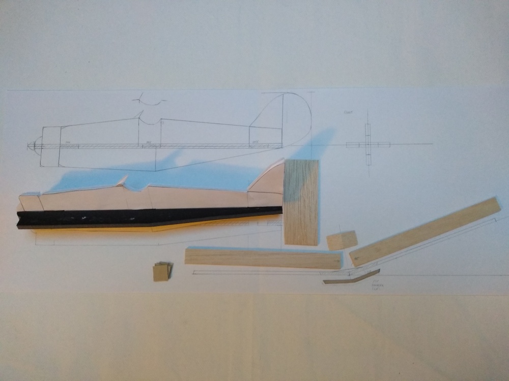
Just to finish, I’ve also been balancing the ATOM autogyro blades, so I’m going to cover these soon. It’s almost at the flying stage now.

Cold, Grey and Windy

IMG_20161127_103419.jpg

The weather wasn’t exactly great for flying this weekend, but I managed to get in four flights with the RS352. I was joined by a guy with his girlfriend who flew a small high wing electric glider once, before deciding to give up and go home. I don’t know what it was, but it had a green wing and white fuselage. At this point something spooked the deer and they all came over to hang around with us. The picture really doesn’t do justice to how close they were. Then a little bit later I saw an electric bike coming across and its owner produced a tiny 5g helicopter out of his pocket. I had assumed he had the Taylorcraft on the back of the bike, but the rear carrier was empty. Obviously it wouldn’t fly in the windy conditions, but he told me he had intended to bring his big electric glider, but it was too much of an effort to get it on the bike in the now rather marginal weather conditions. He gave up and went home to the warm after a bit, so I was left on my own with the deer again, plus a few tourists.

In terms of the flying, there was some strong turbulence and it wasn’t a day for doing much other than just keeping it in the sky. I did turn up the elevator movement for flight 3, going from 60% to 70% on the ATV as I was trying to get it to harrier. I can’t say I noticed much difference as the weather was really going down hill at this point. I was even using clear glasses for some of the flights, it was that bad (I almost always fly wearing sunglasses). My main concern was the jittering that I’ve been getting on the control surfaces sometimes. On switching the aircraft on for the third flight, the right aileron went all the way up and stuck in position. I switched off and on again and everything was fine. I couldn’t find any fault. Then, after the flight, I put the transmitter on the floor to switch the aircraft off and the jittering started again. Same problem with the transmitter on the floor when switching on for the next flight. It looks like having the transmitter on the wet grass (on a plastic sheet obviously) is affecting the signal. This is not something I’ve seen before, so it needs a bit more investigating. If it persists, I might either swap the radio or the four servos for a different brand as I’ve never been completely happy with the combination of the Futaba R617FS and Hitec HS65MG servos. Either component on its own I have no problems with, they’re both rock solid quality pieces of kit, it’s just the combination of the two in this installation that’s been giving me problems.

That’s not the last piece of flying I’m doing this week, as we’re running another Drone Masterclass on Wednesday evening. I’ve been trying to 3D print frames all week and failing.

IMG_20161127_161217.jpg

Eventually, out of sheer frustration, I’ve decided to take two of the partly complete frames and glue them together to make something that works as a 100mm sized quadcopter. This is intended to fly with my EVO F3 Brushed flight controller to make an FPV micro quad. The only problem I had was working out how to add the motors, given that the 3D print kept failing before it got to that point. I was going to use plastic tubing, but, when I was thinking about how to hold the motor mount in the centre of the prop guard, it struck me that I could use the plastic from an old propeller. I’ve got loads of these green plastic propellers that I’ve broken and was looking for something useful to do with them. It’s a bit of an experiment, but I’ll have to give it a try and see how it works out. This might just be a genius piece of recycling?

Hello Angus

Angus is the first big storm of the season, and, although it’s almost blown itself out overnight, it’s still wet and very windy this morning. In other words, I’ve been building stuff.

First, there was the 100mm quadcopter X-Frame which I 3D printed at work on Friday. This took the entire day to print and then I discovered that the model was completely welded to the raft. I shouldn’t have printed it on a raft, although the idea is that it allows the model to be removed from the 3D printer more easily. The problem here was that the raft didn’t separate from the model and I spent most of Saturday morning hacking all the excess plastic off with my Permagrit file. We need this frame for an event we’re running at the end of November, so it needed to be done.

That then got me to thinking about whether I could build my own design micro quadcopter frame and build it in less time than this one took to 3D print. So, on Saturday afternoon, I built my own one from plasticard and white foam.

Basically, it’s just black plastic stuck onto white foam to give it rigidity. The way I made it was to make two straight arms with black plastic top and bottom. Then I cut a hole through the white foam in the middle of one and pushed the other through to make an “X”. You can see where the plastic overlaps in the picture. With the benefit of hindsight, it might have been better to cut a top and bottom “X” out of the plastic and make the top and bottom a single piece? That would have allowed me to add some more material in the centre where the flight controller will sit, but I quite like it the way it is.

The interesting thing is that this took less time to build than the 3D printed model took to print and what’s more, it’s also lighter.

As you can see, my frame is 3.8g lighter. I just can’t figure out how to make the blade guards at the moment. You can also see that it’s slightly bigger than the blue frame, which is to accommodate the larger and more efficient 75mm props. I got the flight controller and radio working last Sunday evening, which was quite an impressive feat. It took me quite a while to figure out how to bind my Futaba Field Force 8 with its Frsky DFT module. You first have to press the button on the back of the module while switching on the transmitter. This puts it into binding mode, which is confirmed by a constant beep, beep, beep. Then you power on the QX908 receiver while holding down its bind button, keeping it pressed until the green light goes solid. Disconnect the power from the receiver, then turn off the transmitter, power everything back up normally and they should be bound to each other. I was then able to see my control inputs in the Cleanflight application on the computer when the flight controller was attached via USB. Once I have a quadcopter that’s flying with the FPV working again I’ll do a full build article. At this point I discovered that the leads from the motors wouldn’t reach the flight controller and decided that adding plugs and sockets as we do for the HubSan assembly kits would be a good idea while I’m experimenting. I don’t have any left, so I’m going to Maplin tomorrow. This only adds less than 1g in weight, so it’s not a huge penalty. I might rethink the motor attachments, though, as I’m not completely happy with just pushing them into foam. That’s where the fun is in making your own quadcopter frame.

I still have the preparation to do for the “Drones Masterclass” that we’re running in a little over a week, so I’m probably not going to get much more building done today.


Ripples in the Grass

It’s a lovely sunny morning, but it’s so windy that you can see waves being created as the wind blows the blades of grass in gusts. Yesterday was even worse with 50 mph winds, so I wasn’t expecting to do any flying outside this week.

I know I said I was finished with quadcopters for a now, but events turned out slightly differently. We have a 3D printed frame for a micro quad that I need to build for work, so I spent Friday evening cleaning up the 3D printing defects and Saturday de-soldering the PCB from my broken HubSan X4.

IMG_20160205_203059.jpg

The 3D printed frame and four 55mm props for scale. Diagonals are 100mm.

IMG_20160205_212754.jpg

With the motors added.

After lifting the PCB out of my HubSan and soldering 8 connectors for the motors, the final result looks something like this:

I’m very happy with the result, apart from the fact that my HubSan elctronics just refuses to work. I knew this before, which was the reason why I was willing to transplant it into another frame for a test. Sometimes it would work fine, then die as soon as you spun the props, and other times it worked perfectly. In other words, intermittent. The trouble is that I can’t get it to work at all now, apart from a brief glimpse of life last night. It must be a cracked PCB or bad solder joint somewhere, but I just can’t seem to fix it. Anyway, when it did come on I proved that there was enough power for it to fly when it flipped over and tried to take a chunk out of my finger. That’s what I like about this size of quad. It feels like it’s powerful enough to damage your fingers and it hurts, but it’s actually perfectly safe. Just what we need for a bunch of 13 year old students.

Lots of New Bits

Lots of new flying stuff to play with.

Lots of new flying stuff to play with.

Today my latest order from Robot Birds turned up, which is pretty good when you consider that I ordered it on Friday and here I am unpacking it on Monday evening.

I needed some epoxy to stick the tail on my autogyro and I’d given my last tube to a certain person to fix his radio controlled range rover. I’m going to to another blog post later about how I fixed the bell crank on the ATOM, but there’s obviously more in the box than just glue. I know I should really finish the autogyro first, but it’s close to flying and I had another project that just couldn’t wait.

It should be obvious from the photo that it’s a 250 size quadcopter, but there’s no frame as I wanted to try something a bit out of the ordinary. You see far too many of these “radio controlled car” aircraft which people have just bought and screwed together. The design isn’t completely ironed out yet, but I’m definitely going to build something unusual.


Can you guess what I'm making?

Can you guess what I’m making?

So there you have a quadcopter with all the parts laid out ready for soldering. But I promise that I’m going to finish the autogyro’s head and tail bits with that “z-poxy” epoxy resin that’s hiding in the bottom of the box. OK, so there are 12 props in the picture, but I bought some different pitch ones and the radio is coming out of my flying wing temporarily. It should be fun programming the NAZE controller and I also have another 10 degrees of freedom sensor board which I’m keen to try out with the Arducopter software in an Arduino Nano. The controller here is a really fast one, so it should vastly out-perform the Nano. It was designed to be a test bed to for experimentation though. I’m really not planning on racing it.

RCM&E Atom Build

I woke up to thick fog and freezing conditions this morning, so no flying this week.

I really need to get on with building the RCM&E Atom as I haven’t touched it since before Christmas, despite the required spruce and plywood supplies turning up from SLEC the week before. Their mail order service was certainly very prompt as I was worried about getting caught up in the Christmas mail order chaos, but it arrived in a couple of days.

My main reason for writing this article, though, is to prevent other people from making the same stupid mistake that I made. Now, I’ve built a couple of dozen aircraft from ARTF through to scratch built own designs, so I’m not a complete novice, but I must be getting out of practice. I could try and blame the lack of 3D construction diagrams with the ATOM plans, but the truth is I measure the wood wrong. The photo below shows the problem:

Looking from the back at the sandwich of B1, B3 and B4, plus sides

Looking from the back at the sandwich of B1, B3 and B4, plus sides

Back view of the fuselage with the sides removed

Back view of the fuselage with the sides removed

The base piece, B1 is 5mm balsa, along with B3 which sits on top. Then the top piece, B4 is 3mm. In the photo you can see B1+B3+B4 in the centre with the pencil drawn vertical datum lines visible going up along the end of all three pieces for alignment when glueing. The two sides aren’t glued at this stage and you can see the doublers, D1, left and right sitting on top of B3 and forming a nice square box. It wasn’t always like this though.

My mistake was that B1 and B3 are from the same stock, which isn’t exactly 5mm deep. Either my eyesight is going, or I didn’t measure it properly, as it’s about 0.75mm thicker than it should be, so 2×0.75mm is 1.5mm and the extra height meant that with the doublers, D1, glued to fuselage sides, the sides didn’t reach the bottom. Without any construction drawings on the plan, it took me a long time to work out what was wrong and how everything was supposed to fit together, but then that’s half the fun anyway. I like the idea of the plans being a bit “open ended” as I always like to tinker with things, so this isn’t a criticism, just a bit of advice for anyone else building it – measure B1+B3 together!

Anyway, my solution was to place the base on the flat building board and offer up one of the sides. Then I drew a very fine pencil line along D1 using the top of B3 as a guide. Placing the fuselage side flat on the worktop, I cut very carefully just inside the thickness of my line to remove about 1.5mm from the bottom of D1 so it now fits as in the photograph above. Then I repeated the process for the other fuselage side.

OK, so everything now fits together and I think I understand where all the remaining pieces go, so the everything should just fall into place. I won’t forget to double check all the angles, though, as the modified D1 might have some consequences for the former and mast angles. And the hole is obviously slightly bigger than my 5mm square spruce strip.

IMG_20150104_162719 IMG_20150104_162746